User Tools
Sidebar
Hosting an xBee network off a remote Wiznet card
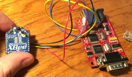
 XTension supports connecting most of it’s interfaces either directly through a serial port or over an IP network pipe. So even though it has always been theoretically possible to host an xBee mesh network off an IP card I’d never actually tried to do it before. There are 2 reasons that I can think of immediately where you might want to do this rather than just connect the host xBee via a usb adaptor to the host computer. In my case the location of the computer means that several xBee radios would be necessary to extend the mesh network to where it’s actually needed and it’s more cost effective to use a wiznet adaptor to start the network where it will be actually used. It may also be useful to have the xBee network remote to the entire system which would also work just fine though if the internet connection goes down it would stop to function till the connection comes back up. Never the less sometimes this might be exactly what you need to do.
The xBee serial requirements are 3.3v TTL level serial. You cannot just connect an RS232 cable to an xBee nor even connect it to a 5v microcontroller like most Arduino (though there are 3.3v Arduino boards with different processors, or the regular ones can be run at a slower speed at that voltage) for most connection tasks you can use one of these excellent carrier boards from Adafruit They provide the 3.3v power regulation for powering the xBee as well as voltage shifting to connect to 5v serial from an arduino. I’ve got half a dozen of these in service around here. So my first thought in connecting these to a Wiznet card was to use this and find the TTL level serial output on the wiznet. This didn’t work…
It turns out that the wiznet cards are already 3.3v on the board and shift themselves up to RS232 levels for the DB9 plug. They do bring these 3.3v TTL serial out to pads on the back and you can also tap their own 3.3v regulator output from the programming header so a separate power supply for the xBee isn’t necessary either. You can use the much simpler xBee breakout from SparkFun to connect. It’s only $3 and has no onboard anything. You will also need 2 xBee header sockets Resist the temptation to just solder the xBee directly to the breakout board! The xBee must be removed from the board to be reprogrammed or for firmware upgrades and such.
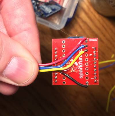
You need 4 connections to the xBee breakout board. Here you can see mine with some hot glue to act as strain relief until I get them mounted properly.
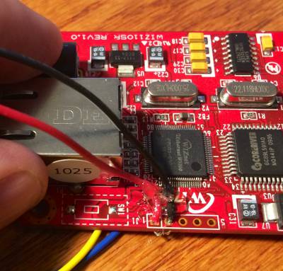
- pin 1 to Vcc which goes to the square hole in the unpopulated programming header on the Wiznet
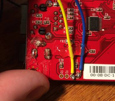
- pin 2 is “DOUT” which goes to J5 on the back of the Wiznet
- pin 3 is “DIN” which goes to J4 on the back of the Wiznet
- pin 10 id GND and goes to the pin next to the Vcc pin on the Wiznet
A closeup of tapping the 3.3v power from the Wiznet card. In my testing here the regulator on the wiznet seems to have no trouble providing enough power to run the xBee. This is a revision 1.0 wiznet card so all these things may change in the future, always verify voltage levels before plugging in your expensive xBee! This is labeled as “J1” on my card and pin 1 is +3.3v and pin 2 is gnd.
On the back of the wiznet are 4 pads. J4 should be connected to “DIN” or pin 3 on the xBee breakout, J5 should be connected to “DOUT” on the xBee breakout. These are the TTL level serial output pads before the serial goes into the level shifter to turn it into RS232. J2 and J3 seem to be directly connected to the power input barrel as on mine they appear to carry the 5v that I was supplying to the Wiznet.
Setup the xBee as you would when directly connecting it to XTension. Zigbee network coordinator, 57600 baud, no flow control, give it a unique network address. Then use the xBee configuration utility to setup the wiznet card with a static IP address and any high port number you wish, the default is 5010 which is just fine, same baud rate, no flow control and most importantly “server” mode in the Remote Host tab. Then you can connect to it by selected “remote TCP address” from the serial port popup in XTension.
You are now hosting a remote xBee network connected over TCP.


