User Tools
Sidebar
Table of Contents
Lightning Sensor
 NOTE: This tutorial was originally written for the Tautic breakout board, unfortunately that is no longer available. I believe that the Thunder Click board will function exactly the same and has the same connections.
Recently Franklin released a very interesting chip for sensing lightning strikes via the RF radiation they create. You can read more about the chip itself here unfortunately only available in tiny non-human solderable surface mount or via very expensive demo kit.
Then there came breakout boards for the chip that exposed it’s connections for regular humans to be able to work with. The connections are still not amenable to connecting directly to a computer and require an arduino host to translate that into serial data that XTension can work with.
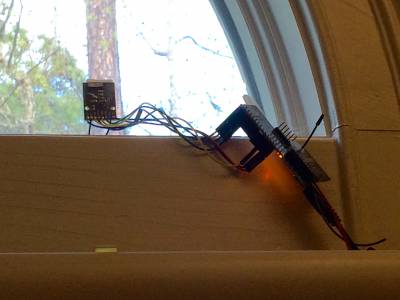
It’s tempting to just use a regular arduino and plug it’s USB port into the computer for communications, however in my testing the sensor was unable to see anything at all when inside the house and in close proximity to the computers. The device really needs to be mounted in a window, or in an enclosure outside with some distance between it and all your computers and power supplies. Mine lives with a bit of 3M contact foam tape sticking it to a window in my office and works great there. See picture below.
In this tutorial we’ll be using an Arduino Fio to do the local processing. It’s best feature in this case is that it has a built in socket for an xBee radio which is what we’ll be using to bring the data back to XTension. The Fio also has a built in LiIon battery charging system so that you can have it continue to run through power outages that might accompany the storm it’s sensing.
The downside of the Fio is that it does not have a USB interface for programming and you will need A TTL level FTDI serial cable (which is my recommendation) or an equivalent device.
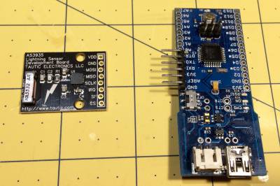
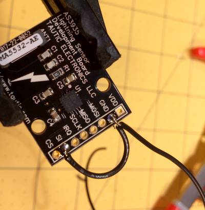
Here’s my sensor, yours may be from a different manufacturer since these are no longer made but the connections will be the same or similar enough as they come directly from the chip and are not breakout specific except for the location.
The Arduino Fio has 2 connections at the bottom. There is a mini-usb connector for power. Please note that this does not provide a serial interface to the computer for programming or data, this is just to run the machine and to charge the LiPoly battery if you choose to connect one. So the board can be powered from any usb charger wall wort. Next to that is the larger white plastic connector for the optional LiPoly battery You’ll also notice the 90˚ angled pins attached to the side of the device. That is where the FTDI cable I linked to above is connected for programming and getting serial data out. The xBee socket is on the reverse side of the board.
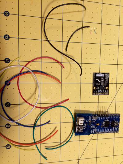
You’ll need 7 short pieces of wire to connect the 2 devices and another shorter additional piece of ground wire for the Tautic board. The newer boards don’t appear to require that. The length isn’t critical, this is going to be 2 separate devices that you have to stick up somewhere and not a simple in the box product. I wouldn’t extend the data lines between the 2 very far though, dont try to solder in some cat5 cable or something to put the sensor outside and the arduino inside or something like that as these are low voltage ttl serial and wont extend long distances.
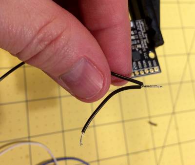
On the Tautic board the ground has to connect to both the “gnd” and the “SI” labeled connections.
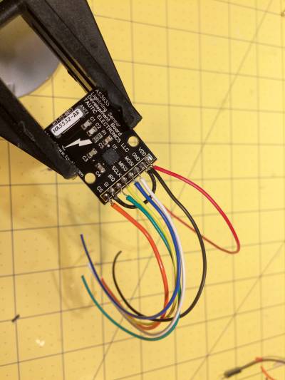
Solder up the rest of the connections to this board.
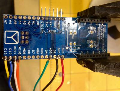
And then you’re ready to connect them to the Arduino.
| Sensor Pin | Arduino Pin |
|---|---|
| VDD | 3.3v or 5v |
| GND | GND |
| MOSI | pin 11 |
| MISO | pin 12 |
| SCLK | pin 13 |
| IRQ | pin 3 |
| SI | GND |
| CS | pin 10 |
Programming the Arduino
If you haven’t already head over to the Arduino Download Page and install the arduino development IDE. There are Mac and Windows and Linux versions.
You may also need to install the Virtual Com Port drivers from FTDI to support connecting to the FTDI serial cable or other means of connecting to the arduino in question. If you’re using a non-fio arduino it may have an FTDI chip on board as well and require this driver, or it may be using built in USB support in the chip and not require any further drivers.
Next you’ll need to get and install the AS3935 chip support library most generously created and open sourced by Raivis Rengelis. The “Download Zip” button is the one on that page that will result in the proper file for installing into your IDE. Installing the libraries differ for different versions of the Arduino IDE but the instructions should be at http://www.arduino.cc/en/guide/libraries
Download the open source code for the arduino program Here
This is not meant to be a tutorial on using the Arduino IDE, but for the simplest install all you have to do is plug in the cable, select the proper serial port from the menu in the IDE and select the proper arduino type from that menu. Then click the program button and you should be done.
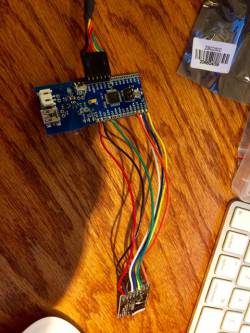
Here’s the arduino with the programming cable connected and the lightning sensor wired in.
Once you’ve got a success message from the arduino IDE you can open the serial monitor. Make sure it’s set for 9600 baud. When it opens it will reset the Arduino and you should see the startup messages in it’s window that show you everything is working. First you’ll see a “Lightning Sensor Startup” message and then shortly there after you’ll probably see a “noise level is too high” message. This is normal at startup no matter what the settings are and even after you get everything else tuned up you’ll still likely get that message at startup and thats OK.
Connecting to XTension via an xBee
If you’re connecting to XTension via an xBee radio you’ll first need to setup your xBee interface in XTension. That means that you’ll need 2 xBee radios to start with as one needs to be the coordinator connected to the Mac. Once you have this working you’ll find lots of other uses for these wonderful little radios. That initial setup is documented here
The xBee setup for this project should be all defaults while verifying that the baud rate on the radio you’re plugging into the arduino is set to 9600 baud. You should also set it’s “PAN” network ID to the same number that you setup in the initial network configuration. You can also just set the PAN ID to 0 and it will join the first network it finds that isn’t encrypted. If you’ve setup an encrypted network then you must set those keys manually into the xBee before trying to connect it to the network.
In testing with many people getting these xBees to work they are very reliable, but sometimes they can take several restarts of the network before they show up for the first time. Keep working with it they will wake up.
Once you power on the device with the xBee configured and installed the same startup message “Lightning Sensor Startup” should show up in the XTension log if everything is working properly.
Creating the units in XTension
You’ll need to create 8 units in XTension for sending configuration to the device and getting information back from it. Then we’ll also setup a few counters to hold data for graphing and I’ll give some examples of alert scripts that wont drive you crazy during a storm with hundreds of lightning strikes.
Since we’re connecting with an xBee these units should be assigned to the xBee interface. The address will start with the last 4 bytes of address of the xBee you’ve placed into the Arduino. For example “AE33FF12” and then a letter “X” and the name from the table below. ie. “AE33FF12XSTRIKE” that goes in the address field and NOT the name field. You can name the units anything you like.
| XTension Address | Dimmable/Non-Dimmable | Description |
|---|---|---|
| DISTURBER | NON-dimmable | this unit is used for tuning. It will be sent an on when the device receives an RF spike that it doesn’t think counts as a lightning hit so you can test the threshold |
| STRIKE | Dimmable | When a strike it sensed this unit will be sent a value that corresponds to the devices estimate of the distance to the strike in km so the unit should also have it’s unit suffix set to “km” |
| NOISE | Dimmable | The noise floor for tuning. Start with a setting around 4 or 5 |
| SPIKE | Dimmable | The Spike Threshold. Start with a setting of 2 |
| MINIMUM | Dimmable | when used in a portable alert device you may not want to be buzzed at the first strike it senses but in our case we want to see them all so set to 1 |
| WATCHDOG | Dimmable | the Watchdog threshold for tuning. Start with a setting of 2 |
| INDOORS | NON-dimmable | If the device is inside, or not in a window, turn this on to increase the gain. Depending on the install you may need to turn this off to decrease the false alarms. I have my device in a window and this set to OFF as it’s close enough to outside. |
| DISTURBERS | NON-dimmable | This stops the reporting of disturbers once you have the tuning setup. You’re not trying to get it to never see a disturber, it will always register these and if left on it will spam your log constantly. So turn off when you’ve got it working to your satisfaction. |
In addition it can be useful to create a few pseudos to hold count information and whether or not you’re sending alerts. In this case the names aren’t important except that the scripts that follow will reference them so if you change the names here remember to also do so in the scripts. In my case I’m sending the alerts to Prowl and since Prowl is one of my favorite things I think you should too but you should be able to alter these to send emails or SMS messages or whatever you choose.
| Pseudo Name | Description |
|---|---|
| ALARM Lightning To Prowl | controls if any alerts are to be sent at all. Useful to be able to turn the system off while working on it |
| strike count 5 min | an accumulator to hold the count of the strikes in the last 5 minutes. Important for graphing and alerting |
| strike count last 5 min | every 5 minutes the 5 min count is moved into this unit. Important for graphing and alerts |
| strike count | a total accumulator for each day |
| strike count yesterday | Yesterdays strike count |
| MODE strike report 5 minute summary | in order to keep from sending thousands of alerts to your phone after a certain number are received in any 5 minute period the scripts will turn this on which changes from alerting with every strike to giving you 5 minute summaries of the storms strength |
Note: the spacing is trying to be full justified in that table above. There is really only one space in between any of the words in the unit names.
Scripts and Events
In the ON and OFF script of the unit you created with the address “STRIKE” above set this script:
--increment the strike count unit
set i to (value of "Strike Count")
set value of "Strike Count" to (i + 1)

--increment the 5 minute strike count
set i to (value of "strike count 5 min")
set value of "Strike Count 5 min" to (i + 1)

--if more than 5 in 5 minutes then switch to summary mode

if (i is greater than 4) then
	if (status of "MODE strike report 5 minute summary") is false then
		turnon "MODE strike report 5 minute summary"
	end if
end if

if (status of "ALARM lightning to prowl") is true then

	if (status of "MODE strike report 5 minute summary") is false then

		set AlertString to "lightning " & (future value) & “km"

		--I am using prowl, if you are using some other method of alerts place it here.
		tell xGlobalScript "Prowl" to SendProwlNotification(-1, (current date) as string, AlertString)
	end if
end if
That will send the alert, if the ALARM unit is on. If more then 5 strikes have occurred int he last 5 minutes it switches to a summary mode and only one event every 5 minutes will be sent with the count.
Now create a global script called “Roll 5 minute lightning” and give it the following code:
--roll the 5 minute value into the previous 5 minute unit and set the current one to 0
set CurrentValue to (value of "strike count 5 min")
set value of "strike count last 5 min" to CurrentValue
set value of "strike count 5 min" to 0

--if there were no strikes in this last 5 minutes then reset the summary pseudo
if (CurrentValue is 0) then
	if (status of "MODE strike report 5 minute summary") is true then
		turnoff "MODE strike report 5 minute summary"
	end if
end if

--if the summary pseudo is on then send a 5 minute summary report.
if (status of "MODE strike report 5 minute summary") is true then
	set AlertString to CurrentValue & " strikes in the last 5 minutes"
	tell xGlobalScript "Prowl" to SendProwlNotification(-1, (current date) as string, AlertString)
end if
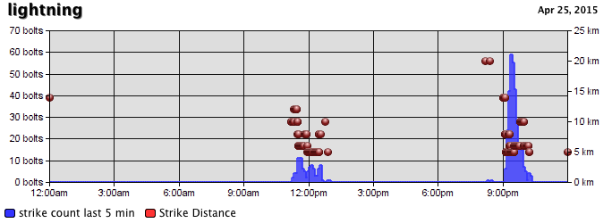
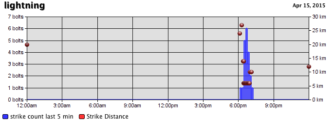
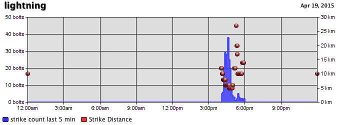
now quit and restart XTdb so that it will pick up the new units and you can begin saving data, getting storm alerts and creating graphs like these:
My final install isn’t very pretty, but it works great stuck to the window:

