User Tools
Sidebar
HAI Omnistat
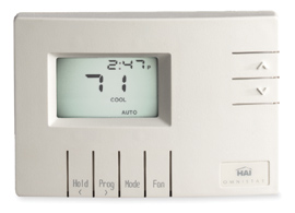
 As of build 826 XTension supports a direct serial connection to a bank of Omnistat Communicating thermostats. Though I only own the earlier models to test with they implement the same protocol as the Omnistat 2000’s and I expect the basic functionality to work fine with them too. If anyone has the newer models and has any problems or is willing to run this to talk to them please let me know as I’d love to know for sure that they work or to work out any issues.
The omnistats require 4 wires of serial data to be run to the stat itself. This can be a bit of a pain but if you can get 4 wires to them the reliability of the connection surpasses any wireless or powerline protocol. I used a run of cat-5 cable 2 pairs of which run back to the computer and are connected to a standard serial port. There are detailed connection diagrams in the documentation that comes with the thermostat. Only a regular RS232 serial port is required and XTension supports the connection either via a USB/Serial adaptor or an Ethernet to serial port like the Wiznet or the port on the Barix/Barionet devices. Up to 10 Omnistats are supported on a single port, or you can configure individual ports for any combination of them that you choose for faster response times and scanning.
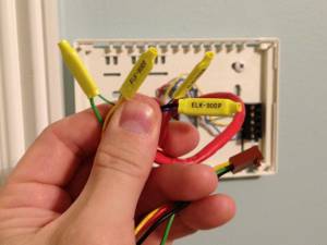
 Wiring them is easy they come with a 4 pin connector and crimp connectors to connect them to the serial wiring. Wiring the connections to the furnace are identical to any other thermostat. The omnistats require a 24v system which is common. If you have a non-standard system a relay isolator is available that can connect them to anything. Please note that while it is low voltage you must turn off power to the furnace while you do the install. If you were to momentarily short the voltage you could either blow a fuse inside the furnace or require the visit of an HVAC contractor to replace the tiny transformer. Also intermittent connections to a heat pump or AC compressor could cause the motor to burn out or significantly reduce it’s useful life. Turn the power off while you change the thermostat.
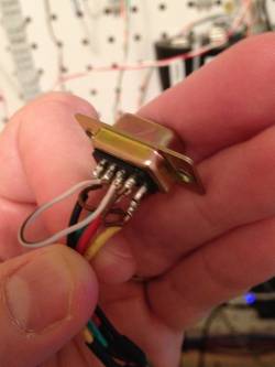
 Making the serial connection to a computer is not documented, you could buy the programming cable that is part of the installer kit, but this is not necessary. Making them talk requires shorting a few of the pins together for whatever reason. This is what mine looked like after a lot of resoldering and experimenting before I potted it in hot glue and installed a hood. I would never have figured out the sequence without Tom Dowdy’s site who originally figured it all out. Here is the wiring sequence:
- wire RTS and CTS together, thats pins 7 and 8 on a DB9 plug
- wire DCD, DTR and DSR together, thats pins 1, 6 and 4
- pin 5 is ground connect to the black wire
- pin 4 also connects to the yellow wire
- pin 3 is transmit, connects to the green wire
- pin 2 is receive, connects to the red wire
so yes, pins 1, 6 and 4 all connect to the yellow wire. And you have a separate loop connecting 7 and 8. That last may not be necessary depending on the interface but I did it and it worked.
Like many embedded devices that want to make an RS232 compatible serial output the Omnistats use power from the DTR pin to power the level shifters on their boards. Not all USB or Ethernet serial adaptors can supply enough voltage or current to power them. In my case even with a proper FTDI chip on the interface I had to wire +5v directly to the DTR pin. If you’re using an ethernet/serial adaptor then you may also have to make this alteration. This this example is for connecting to a UPB interface module, it should work exactly the same for connecting an Omnistat to a Wiznet ethernet/serial card wiznet 5v dtr connection
If you’re using a USB adaptor no other serial settings are necessary, but if you’re using an ethernet/serial adaptor then you’ll need to set it to 300 baud, 8 data bits, 1 stop bit and no flow control. If you have the option of turning on the DTR pin then that might be helpful.
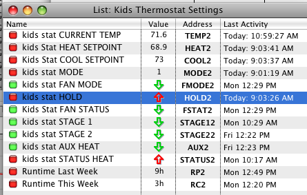
Once you have a serial connection to the thermostat in XTension visit the preferences and create a new device interface. From the device popup select Omnistat and from the port popup select either the name of the serial port or remote TCP connection if you used an ethernet/Serial adaptor. Save the new interface and begin creating units for data display and control. The names of the units should be descriptive to you and must be unique in the system. I recommend a description of the placement, the fact that it’s a thermostat and then the function of the thermostat. For example “kids rooms thermostat CURRENT TEMP” but use what you like. The address of the unit is how the data finds it’s way to the appropriate unit and should be the short text descriptor as below followed by the stat ID number that is set on the stat. Since You can have multiple omnistats on the same port they are each assigned an ID number at the stat that must be unique on the network. In my case the omnistat I’m using is at ID2 since it used to be part of a larger network at the old house and I have not bothered to change it.
The clocks in the Omnistats will be regularly updated to the clock in the computer automatically.
Here is the list of units and the addresses to use for each stat on your network. The names can be changed, the addresses cannot.
- CURRENT TEMP
- address: TEMP2 (the word “TEMP” followed by the ID number of the stat)
- dimmable (in order to store a number as opposed to just on/off)
- receive only (you cannot change this number and it will only confuse it to try)
- ignore clicks in list (stop you from accidently turning it off by doubleclicking the list)
- FAN STATUS
- address: FSTAT2 (the word “FSTAT” followed by the ID number of the stat)
- not dimmable (stores only an on/off)
- receive only (use the fan mode to change the mode, this tells you if the fan is currently running)
- ignore clicks in list (keeps you from accidentally getting the database out of sync)
- STAGE 1 RUNNING
- address: STAGE12 (“STAGE1” followed by the ID number of the stat, 2 in the example)
- not dimmable (only on or off)
- receive only (you cannot control this)
- ignore clicks in list (you really cannot control this)
- STAGE 2 RUNNING
- address: STAGE22 (“STAGE2” followed by the ID number of the stat)
- not dimmable
- receive only
- ignore clicks in list
You can ignore this unit if you do not have a 2 stage system but you will receive a status update for it in the log during startup.
- AUX HEAT
- address: AUX2 (“AUX” followed by the ID number of the stat)
- not dimmable
- receive only
- ignore clicks in list
This will alert you in the event that your auxiliary heat in a heat pump system was run. If you do not have a heat pump you can leave out this unit but you will receive an update for it in the log at startup time.
- STATUS HEAT
- address: STATUS2 (“STATUS” followed the ID number of the stat)
- not dimmable
- receive only
- ignore clicks in list
This unit tells you what the stage1/2 units are telling you. If this unit is ON then the stage1/2 units are telling you that the heat is running. If this is off then they are telling you the AC was running. This is necessary to see what is actually happening if the stat is in AUTO changeover mode. If it’s not in auto then this will always reflect the MODe setting of heat or AC.
- RUNTIME THIS WEEK
- address: RC2 (“RC” runtime current, followed by the ID number)
- dimmable (it needs to hold a number so it must be dimmable)
- receive only
- ignore clicks in list
- RUNTIME LAST WEEK
- address: RP2 (“RP” runtime previous followed by the stat ID number)
- dimmable (needs to store a number)
- receive only
- ignore clicks in list
The runtimes as saved here are in hours.
The rest of these units are used to actually control the thermostat.
- HEAT SETPOINT
- address: HEAT2 (“HEAT” followed by the ID of the stat)
- dimmable (to store a value)
- COOL SETPOINT
- address: COOL2 (“COOL” followed by the ID number of the stat)
- dimmable
- MODE
- address: MODE2 (“MODE” followed by the ID number)
- dimmable (0=off, 1=heat, 2=AC, 3=AUTO)
- FAN MODE
- address: FMODE2 (“FMODE” followed by the ID number)
- not dimmable (OFF=auto, ON=ON)
- HOLD
- address: HOLD2 (“HOLD” followed by the ID number)
- not dimmable
stat will not make any changes to the temp by itself as long as this is on. Overrides it’s internal programming. (I keep mine on hold all the time and only make changes through the computer)
- Outside Temperature Display
- address: OTEMP2 (“OTEMP” followed by the ID number)
- dimmable to hold a number
If you do not have an outdoor sensor directly attached to the stat then you can use this unit to send an outdoor temp for display at the stat. Link this to however you measure an outside temperature or even to a weather forecast and your stat will alternate between showing the current temp inside and the outside temp.
- Time To Filter Change
- address: FILT2 (“FILT” followed by the ID number)
- dimmable
This is a bit odd as it’s the number of 24 hour periods left in runtime before the filter change reminder will start to flash. The documentation gives the default for a 30 day filter at 10, or 240 hours. This number will update regularly from the stat and if you set this value (max 255) from XTension the new value will be sent to the stat, resetting the filter change reminder or just changing the counting towards it.
The Omnistats use a lookup table of temperatures to translate an internal index number to a temperature. They will round the values for display on the thermostat if it has a decimal. It can also only be set to these specific indexs. If you try to set a temperature that is not on the list, 70F will become 69.8 in the XTension display but will display as 70 in the thermostat. But dont be surprised to see a small discrepancy between the unit display in xtension and what the stat says on the wall.
In XTension you’ll end up with units like this, I would make a new list for each thermostat for easy review and remote control. 
The stat supplies other data about it’s programming and time left before a filter change and such. Eventually I will bring out this data as well as an interface for programming it. But I’ll do it sooner if someone asks for it.
The last gotcha that I’ve noticed with these is that there is something about the serial connection that gives fits to Keyspan USB/Serial devices. I had trouble years ago with my keyspan adaptor and switched to an FTDI chip based one without difficulty. Lately during the course of developing this new version I used a keyspan 4 port adaptor that had been serving up 2 other serial devices without difficulty for years and 2 days later it took the whole device down including the other streams. It had to be unplugged and replugged to come back to life. I dont know what is going on between keyspan adaptors and omnistats, but I would recommend an FTDI chip based adaptor for these devices.
Make sure you’ve read the General Thermostat Notes

