Table of Contents
Smart Electric Meter Reader Kit
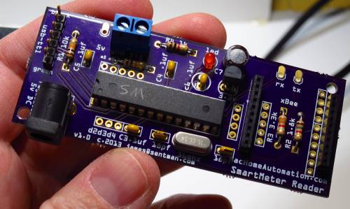
The new smart meters that are being rolled out across the country offer a lot of reporting info on your electric use, but it can still be desirable to get that data in realtime into XTension. This open source, arduino compatible kit can read the calibration pulses that these meters provide to give you a realtime picture into your electric use.
The processor comes fully programmed and ready to be added to the board. Should you wish to make your own changes to the software the firmware can be downloaded Here. The build instructions can be downloaded from Here all is simple through hole soldering and should be within the grasp of any kit builder. Everything you need to know about compatibility and construction is in that file.
This kit uses an optical sensor to read pulses from specific kinds of meters. The sensor can be attached to the outside of your meter case safely. There is no need to call an electrician, open the service panel or shut off the power to install it. The downside of being an optical sensor is that bright lights or poor alignment may cause it to lose pulses and make incorrect estimates of power usage. The firmware is constantly monitoring the ambient light level and adjusts over time to dynamically find on and off levels for the pulses. This works very well in both full sun and in full darkness, but does mean that the actual timing of the pulses can fluctuate as the chip is busy with other tasks. The immediate power usage value should be considered a good estimate. The actual pulse count showing how much power has been used should be very accurate.
Not included in the kit are the 2 xBee radios necessary to get the data back to XTension, a regulated 5V power adaptor and an enclosure. You will need some velcro, or 3M adhesive strips to hold the sensor to the meter and some wire to connect the sensor to the radio board. A single twisted pair harvested from an ethernet cord is fine.
Sample Output
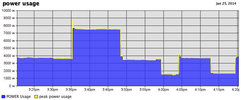
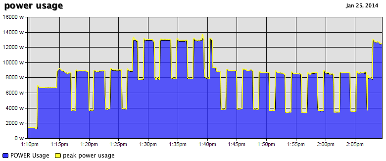
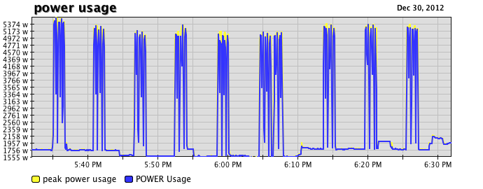
By putting the data into XTension and using XTdb: Database and Graphing for XTension to draw graphs you can see things cycling on and off.
 This is just my AC cycling on and off. It’s interesting to see the peak levels in yellow that show that starting up the compressor takes quite a bit more power for a moment.
 This is my electric dryer cycling on and off to maintain temperature.
 And this is my electric oven which has a very unusual cycle. It pulses it’s elements and doesn’t go all the way on for any length of time.
Compatible Electric Meters
At this moment the following makers and models of electric meters may be compatible.
| make and model | where to mount the sensor | which sensor to buy |
|---|---|---|
| Sensus iCon iSA21 and iSA2 | centered above the display | use sensor 2 |
| Itron or Schlumberger C1S, C1R, C2S or C2SR | on top of can pointing up | use sensor 2 |
| GE i-210 or 210+ | front panel below to the right of the display | use sensor 1 |
| Elster R1S/REX | left of the two LED’s below and right of the display | use sensor 1 |
| Elster REX2 | left of two LED’s below and right of the display | use sensor 1 |
| Itron SS1S1L | to the right of the display | use sensor 1 |
| Echelon E2L model 83020-2680A, EM50202-NES | top of 2 LED’s right of the display | use sensor 1 |
Other models may be compatible, and these listed may have their calibration output pulses turned off in firmware. If you wish to verify that your unlisted model is supposed drop me an email and we can figure something out.
Configuring the xBee Radios
If you haven’t setup an xBee network yet the first thing you’ll need to do is to get an xBee breakout and an xBee coordinator connected to your XTension Mac. You can read the detailed instructions for doing this on the xBee Radio Interface Page.
Please remember that XTension works only with Series 2 and 2B radios. NOT Series 1 radios. However it will work with any antenna or output level combination or regular or Pro labeled modules.
The xBee radio that you install into the sensor should be configured to join the same network “PAN” ID that you setup in your coordinator. All other parameters should be left as the default except that the baud rate communicating to the sensor should be set to 57600.
Once you have the radio configured and installed if you apply power about 3 seconds later you should see “XTension Smart Meter Reader version 2.0 Startup” written to the XTension log if everything else is working. You can test this before you attach the hardware to the meter.
XTension Configuration
The sensor sends 4 data points to XTension that you need to setup units for. If you’re using the xBee network then the units should be assigned to the xBee interface with an address that starts with the 4 hex bytes of the xBee address that you installed into the sensor. Then a letter X and finally the name of the data point. All units should be “dimmable“ and set to “receive only” with “ignore clicks in list” turned on.
If you’re using an alternative method to receive the serial data then use an Arduino interface and the address should be just the name without any xBee address.
| Example Unit Name | xBee address | Arduino Address | Description |
|---|---|---|---|
| Elapsed WH | <xbeeaddress>XWHTOTAL (ie: 4031551EXWHTOTAL) | WHTOTAL | holds the number of watt hours that have been used since power was applied or you sent the nightly reset command. |
| Power Usage | <xbeeaddress>XINSTANT | INSTANT | the average instantaneous estimate of the load in watts over the last 5 seconds |
| Peak Power Usage | <xbeeaddress>XPEAK | PEAK | the highest wattage reading since the last packet was sent |
| WH Counter | <xbeeaddress>XWHINSTANT | WHINSTANT | the number of watt hours used since the last packet |
You may also wish to create some pseudo units to hold other data. You should create a pseudo unit called “wh used yesterday” to hold yesterdays value for graphing and database use.
You should create a global script called “rollover elapsed power usage” and set it to run every night just before midnight. (this way on graphs the “wh used yesterday” will show as the total for today)
set value of "wh used yesterday" to (value of “Elapsed WH")

--reset the counter for the next day
send data “<xbee address>;R" interface "xBee Main”
that last send data line will reset the total being sent from the board back to 0. Replace the <xbee address> with the 4 byte hex address of the xBee connected to the sensor.
Purchase
The attachment plastics for the meter sensor are 3D printed on demand so there may be a couple of day delay before shipping.
If you would prefer to purchase pre-configured xBee radios I would be happy to set those up for you as well, please contact me regarding the type and number that you need.
Download the build instructions Meter Reader Assembly (PDF)
If you wish to work on your own interface to this device or re-program it please visit the Details page
